.................................. Return to Sumner's Home Page....
Return to N Scale RR Main Menu.............. Return to Locomotive Menu
=========================================
..............Previous Page..............................Next Page If There Is One
=========================================
….........…..--- Pt. 7 --- N Scale DDA35 & B Build ---
=======================================================
NOTE: This is not an accurate build of a DDA35. I've tried to 'get close' but at almost 80 don't want to spend a ton of time on this. I need to get back to laying track, adding scenery and finally running a train or two.
=======================================================
Getting close to installing a LokSound 5 Nano sound decoder. First though the frame needs to be shortened so that the GP35 cab can be glued to the DD35 shell and the frame ends up fitting the shell.
I slid the cab on one end of the frame and the DD35 shell on the other as far as they would go. The distance between them is the amount the frame needs to be shortened for the two to meet. I took a measurement with the dial calipers and added about .025” to the distance and used that for how much needed to be removed.
I still had the frame in the mill from milling out the area for the speaker and decoder so decided to 'carefully' see if I could mill out the center section with the frame being held by not much in the vise. A cut was made through the frame on the right side (above) and everything held steady so I moved to the left cut.
The left cut also went fine. I made very shallow cuts on both sides but even shallower on this side as now the frame wasn't held in the vise by much of a surface and I didn't want the end mill to grab and screw things up. I also have the mill turned up to about at fast as it goes (over 2000 rpm – the mill has variable speed and I don't have to change belts/pulleys).
Once the frame is shortened it becomes four frame pieces vs. two. Two pieces on each side. The pieces on each side need to be tied together for strength and to connect the track power pickup from the two trucks for each side. Also the two side frames need to be held together as the screw that use to hold them together in the middle of the frame got cut out with the section of frame that was cut out.
I decided to use a piece of PCB (printed circuit board) to do this and did a quick sketch of what I wanted with some measurements (show above). I drilled 8 holes but only ended up using 4 of them. I also filed an electrical isolation gap down the middle (shown in next picture) as the two frame halves need to be isolated from each other because they pick up the track current from the two track rails.
A similar gap was filed into the bottom of the PCB. I like using PCB like this as it is easy and quick to work with and very cheap. This PCB, besides tying the 4 frame pieces together on the bottom also ties the two frame pieces on each side back together electrically. I drilled and tapped the frame for the 2-56 screws.
After putting the PCB in place and later with the one on the top I checked to make sure the two pieces on each side were connect (had continuity) but that the two frame halves weren't connected electrically (didn't have continuity).
Moving on to tying the frame pieces on the top something similar was done. Again PCB was used and taken advantage of. Two center sections were created and presented a place that the motor and decoder motor wires could be soldered to. They were separated from the frame halves by cuts across the PDB right in front of the four frame pieces. Now two of the pads on one end or the other of the PCB could be used to solder the decoder wires that are used for track pickup. This made installing the decoder very easy and fast as four of the main decoder wires that have to be connected could easily be soldered to this piece of PCB board and it also physically connected the four frame pieces together on the top.
The frame was again drilled and tapped for 2-56 screws but used 2-56 flat head screws here for more clearance for the wiring that was going to go in.
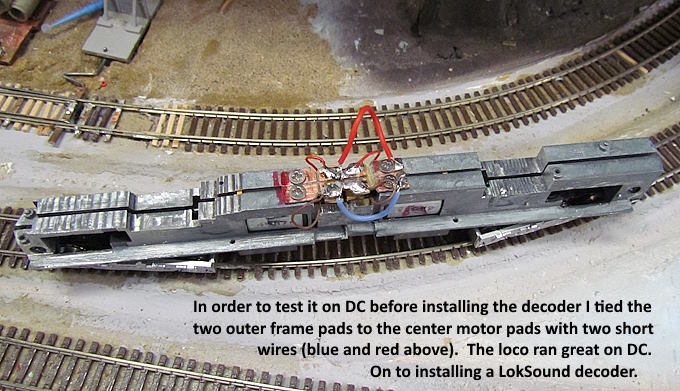
The motor wires from each motor were soldered to the PCB on each side and I added a wire from each side in the center to the two track pickup points on the PCB (blue and red wires above). This turned the loco into a DC loco with the DC current going from the trucks to the frame halves, then onto the center of the PCB board and then down to the two motors. Quick easy way to test the loco with DC on the test track. The shortened frame and motors all worked fine so time onto removing the blue/red wires and installing a decoder.
First though I wanted to glue the cab onto the rest of the shell and needed to strip as much paint as I could off of it before doing that.
After soaking for a little over 24 hours I got as much paint off as what is shown above. More soaking in the IPA wasn't getting any more off so moved on.
If you came into the build here you can go to the start of the build ( HERE ).
(NOTE: Keep in mind that this is N scale and these images if viewed on a computer can be larger than the real thing.)
=========================================
…..............................................Next Page If There Is One